Schematic
— hardware — 2 min read
Schematic
This is built in kicad. Get the schematic and pcb files here on github
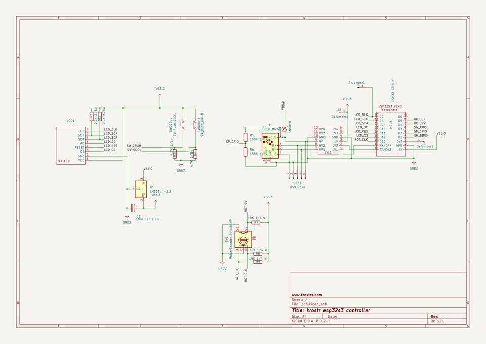
- Note that depending on which esp32 you use you will need to remap the GPIOs.
- Schematic uses a 18 pin board, and also supports a 16 pin board the esp32c3 super mini.
- if you use the supermini, you will need to add a jumper from the LCD backlight to the 3v
Optional
-
LM1117T-3.3v and the 10uF C1 capacitor You have the option to power the LCD and the rotary using a LM1117T-3.3 or directly power the 3v3 from the esp32. To do this connect J3 from the esp32 to J2. Note that some LCDs dont work well when powered from the esp32.
-
R5, R6 100K resistors - that sense when the unit is self powered. This is actually wasted on the esp32c3 because the self-powered functionality is only supported on with tinyusb which does not run on the C3 yet. This may be useful when using the esp32s3 or you can reuse this GPIO for connecting to a max6675 thermocouple.
Using a esp32s3 zero or esp32c3 zero
Using a zero is slightly more expensive but gives you 2 more pins, that can then let you connect a max6675 or equivalent thermocouple to the controller. The Max6675 needs 3 GPIO pins, so for the 3rd one, you have two choices:
- use the pin SP_GPIO - that is currently used for sensing when the unit is powered by the roaster. Not really used.
- use the pin connected to LCD_RES - you can hardwire the LCD_RES permanently to HI and free up another GPIO.
So technically you can end up with 4 unused GPIO pins when using an esp32s3 zero or esp32c3 zero which you can then use for 1 or 2 max6675 thermocouples or for providing speed control to the drum or something else.